HMI Panels in Practice — How to Choose an Operator Panel?
What an HMI panel is, how it differs from a PLC, and eight criteria for choosing an operator panel — plus how to design a screen operators can read.
The operator panel is the element of a machine with which the operator remains in contact throughout the working shift. Correctly selected and carefully designed, it reduces a changeover to selecting a recipe from a list. A deficient design produces the opposite outcome: operators resort to improvised instructions attached to the enclosure. The following sections address, in order: what an HMI panel is, how the selection of an operator panel proceeds, what information datasheets omit, and how to design an interface that is legible to the operator.
Table of contents
What is an HMI panel and what does it do on a machine?
An HMI panel (Human Machine Interface) is the interface between the operator and the machine: a touchscreen that presents the state of the process and permits its modification. The panel does not perform machine control – this is the function of the PLC. It reads process values from the controller and writes setpoints back to it, while the process control logic should remain on the controller side.
On a typical machine the HMI panel performs four functions:
- process visualisation – temperature, pressure, part count, cycle phase;
- modification of parameters and recipes;
- alarm handling together with alarm history;
- basic diagnostics (a view of the I/O).
There are two exceptions to the principle of locating logic in the controller, and both require verification before a replacement is quoted. The first is all-in-one HMI+PLC units, in which the controller is physically located within the panel enclosure; replacing the panel then means replacing the entire control system. The second, encountered more frequently, concerns panels in which a previous contractor placed part of the logic in panel scripts or macros. In such cases the interface genuinely participates in controlling the machine, and its replacement requires that logic to be reconstructed as well. For this reason we begin by establishing where the program is physically located.
HMI panels and machine safety
One issue is a source of serious misunderstanding: a standard HMI panel does not constitute a safety device. Emergency stops, light curtains and guard interlocks must be implemented as safety functions in their own right – to the Performance Level derived from the machine risk assessment in accordance with EN ISO 13849-1, and independently of the standard control system, so that they remain operative even if the interface has frozen. In practice this requires a safety relay, a safety controller or a safety-rated fieldbus, rather than a graphical element on a touchscreen.
The decisive argument is, however, a formal one: EN ISO 13850 requires the emergency stop actuator to be manually operated, with direct opening action and a latching function – a red mushroom head against a yellow background. A button rendered on a touchscreen does not satisfy this requirement, irrespective of how the output stage is constructed.
Exceptions exist and are worth noting: handheld and mobile panels equipped with an integrated emergency stop and enabling switch, and panels carrying certified safety functions over a safety fieldbus. Such devices are, however, specified as safety components from the design stage; a general-purpose operator panel does not fulfil that role. Compliance matters relating to modernisation are discussed in more detail in our post on machine retrofits.
Selecting an operator panel: eight criteria
Panel datasheets closely resemble one another. The differences that determine the success of an implementation are concentrated in eight areas:
- Screen size, touch technology and legibility. What matters is not the size of the display but its capacity to present simultaneously the information the operator requires. A simple machine with a few setpoints is adequately served by a 4.3-inch or 7-inch panel; visualising a line comprising fifteen or so parameters together with trend charts requires 10 inches or more. Touch technology is at times of greater consequence: a resistive solution functions with any glove and through a protective film, but wears in areas of frequent contact; a capacitive screen is more durable and clearer, yet water droplets remaining after washdown may be interpreted as a touch. Where the panel is mounted outside the line of sight, increasing the diagonal does not resolve the problem – the viewing angles of the display should be verified instead.
- Operating conditions and IP rating. The protection rating is declared separately for the front of the panel and for its rear: the front is exposed to conditions at the workstation, while the rear remains enclosed within the cabinet, so requirements for it are considerably lower. For the front, at least IP65 is normally assumed – dust-tight and protected against water jets; where the workstation is cleaned with a pressurised jet, IP66; and where cleaning is carried out with high-pressure hot water, IP69K. The declared rating is achieved only with the gasket correctly seated and the specified clamp torque observed. Chemical resistance is a separate matter: the IP code does not describe the resistance of the front to cleaning agents, solvents or oils, which must be verified in the datasheet independently. The operating temperature range also requires checking: in an unheated building, winter temperatures may fall below the datasheet value.
- Hazardous areas as a separate category. Where the workstation lies within a hazardous area – whether the atmosphere is gaseous or arises from combustible dust – installation of a standard panel is inadmissible irrespective of its IP rating. It is necessary either to specify equipment certified to ATEX for the zone in question or – generally the simpler and less costly option – to relocate the panel outside the zone. The point of departure remains the plant explosion protection document and zone classification, not the device datasheet.
- Communication protocols and transmission throughput. The panel must support the protocol appropriate to the interface of the controller in use. Controllers from a single manufacturer are frequently offered with several distinct interfaces – serial, fieldbus and Ethernet-based – and a panel prepared for one of them will not communicate with the others. The physical layer must also be taken into account: RS-232, RS-422 or RS-485, termination and connectors. Throughput requires verification as well as compatibility: reading several hundred tags over a serial link operating at 9600 bit/s results in refresh intervals of the order of seconds, which reduces the usability of the interface and causes loss of continuity in trend plots.
- Memory and recipes. Where a dozen or more product variants are manufactured, recipes stored in the panel constitute the least costly means of shortening changeover – one of those measures that raise output without investment in a new machine, as discussed in our guide to automation costs. The number of sets accommodated by the memory and the possibility of exporting them require confirmation: recipes stored solely within the panel are lost together with the device.
- Data and alarm logging. Time-stamped alarm history permits fault diagnosis to be shortened from hours to minutes, although its usefulness depends on three factors: the presence of a real-time clock with battery backup and the manner in which the battery is replaced (once depleted, timestamps cease to be reliable), the capacity of the memory expressed as days of logging before the oldest records are overwritten, and the possibility of exporting data to a USB memory stick or a memory card.
- Ports, expansion and remote access. An additional serial port, Ethernet to the plant network and USB for project transfer constitute desirable provision; reserving one free port is advisable, as the need to connect a barcode reader or label printer arises more frequently than is assumed at the design stage. Where the panel is to be connected to a network, the presence of a web server and VNC should be established. Remote access should be implemented by means of a VPN router, not by forwarding a port to a public address.
- Mechanical fit, power supply and availability over time. The panel cut-out and mounting depth are subject to verification – a new panel rarely corresponds to the dimensions of the aperture left by the previous device, so an adapter plate or a new cabinet door must be allowed for in the quotation. The headroom of the existing 24 V DC supply should be checked, and where the panel is mounted directly on the machine, the permissible vibration level. The period for which the manufacturer declares availability of the series also requires confirmation; a panel represents a purchase with a horizon of a decade, and this criterion is at times more significant than a difference of a few hundred zloty in price.
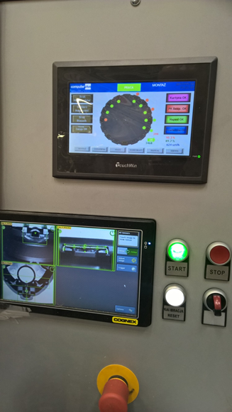
Information omitted from datasheets
Configuration software and licensing
The panel constitutes only the hardware layer; the actual value is represented by the HMI project. The cost of the configuration software, the necessity of a hardware dongle and the possibility of opening the project independently several years later all require confirmation. Software free of licence fees and requiring no dongle reduces the cost of every subsequent modification.
Method and duration of project transfer
Transferring the screens over USB takes approximately one minute, whereas over a slow serial link it may take a quarter of an hour. At the commissioning stage, where the number of corrections reaches several dozen, this difference translates into a full working day.
Behaviour following a power failure
The capacity of the panel to resume operation automatically and to retain its setpoints requires verification. Once power is restored, the machine should start in a safe state and await a deliberate restart, rather than resuming the interrupted cycle. Where the setpoints are physically retained should also be established: the panel generally transmits a value to the controller only at the moment of change, so that if the relevant memory area in the controller is not retentive, the controller resumes operation from zero values while the panel continues to display the previous figure.
Principles of operator interface design
Hardware selection constitutes half of the matter. The other half is determined by the screen design – in our experience it has been the more frequent cause of unsuccessful implementations, rather than an unsuitable choice of panel. We apply the following principles:
- Machine state legible without interaction. An operator entering the shop floor should recognise at a single glance whether the machine is running, waiting, or has been stopped by an alarm.
- Indication that data is no longer current. Interruption of the link to the controller does not manifest itself as a fault – the panel continues to present the last values read, which the operator interprets as current. We routinely employ a watchdog counter and an unambiguous loss-of-communication message.
- Alarm text indicates the required action. The message „Error 217” remains useless. The message „No part in feeder – refill the hopper” enables the operator to remove the cause independently, without engaging the maintenance department.
- Alarm hierarchy and identification of the primary cause. Alarms that stop the machine should be separated from warnings and informational messages. A single fault generally generates a dozen or more secondary messages, so the first event should be recorded and highlighted – it is that event which indicates the cause.
- Three levels of access rather than a single password. The operator modifies parameters within their scope of duties: recipe selection, clearing a counter. The setter has access to changeover parameters. Maintenance personnel have access to timings, calibrations and diagnostics. Each level requires a separate password and automatic logout.
- A dedicated diagnostic screen. I/O status, communication status, running-hours counters and a list of recent alarms gathered on a single screen constitute the element that most substantially shortens fault rectification.
- Touch elements adapted to operation with gloves. Large fields with adequate spacing are required; operating a screen with a wet, gloved hand differs fundamentally from operating consumer devices.
- Confirmation restricted to irreversible operations. For irreversible operations confirmation is justified; applied to every action it becomes reflexive within a short time and loses its protective function.
- A uniform layout across all screens and a maximum of two levels of depth. A function placed in a third-level submenu remains, in practice, unused.
- The terminology of the operator, not the engineer. The appropriate description is „Feeder speed”, not „Setpoint AI3”. Where personnel from abroad work the shift, a second language version should be provided for from the outset – its subsequent addition incurs a higher cost.
- Legibility under actual conditions. Contrast should be assessed at the workstation, under the lighting genuinely present there and from the distance at which the operator will observe the panel – not on an office monitor.
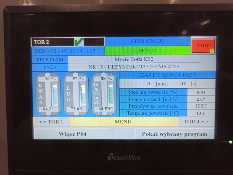
An effective test of the design is assessment of the completed interface by an operator not involved in the implementation. Each hesitation indicates a point requiring correction, and a correction introduced before handover takes minutes, whereas one made afterwards entails a separate site visit.
Xinje HMI panels as an alternative solution
In the implementations we deliver we employ Xinje TS5 series HMI panels, available in a 7-inch variant with a resolution of 800×480 and a 10.1-inch variant at 1024×600. They are built around a 1 GHz Cortex-A7 processor with 128 MB of memory and a display rendering 16.77 million colours with a resistive touchscreen; the front carries an IP65 rating and the supply is 24 V DC. Complete offer, selection guidance and knowledge base: Xinje.pl store (in Polish), run by our company.
Communication provision comprises two serial ports – COM1 as RS232/RS485 and COM2 as RS232/RS485/RS422 – a 10/100 Mbit/s Ethernet port supporting Modbus TCP, and a USB socket for removable media. A significant property is that both ports operate independently, allowing several devices to be served simultaneously. The E, W and 4G variants differ in their external communication: Ethernet only, Wi-Fi and a 4G modem respectively.
The panels are configured in the TouchWin Pro environment. Three properties are relevant to the criteria discussed above: retentive registers, in which recipes and setpoints are held across a power failure; built-in communication status registers, which permit the loss-of-communication indication described in the design principles to be implemented; and support for eight interface languages. A project can be downloaded over USB, the local network or removable media, and can equally be uploaded from the panel – which matters when taking over a machine from another contractor.
At comparable functionality the cost of a TS series panel represents a fraction of the price of an equivalent from a widely recognised brand, which in many cases determines whether a modernisation is undertaken at all.
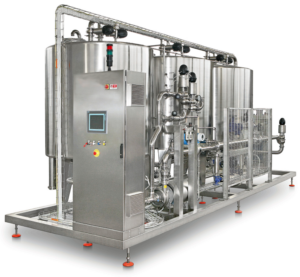
Two examples from practice follow. At a dairy plant a Xinje panel replaced a damaged Siemens panel on a CIP station: the screen layout was reproduced on a one-for-one basis on a display of greater legibility, the alarms and data history were retained, and communication with the Siemens S7-300 controller was established over PROFINET, without intervention in the controller itself. A saving of approximately 70% was obtained against the price of the original panel, with completion in less than a week from order and no requirement for operator retraining, as the screens retained their previous appearance. The details are presented in our project record: CIP station modernisation in a dairy plant. How a CIP station is built and controlled is explained in our article on automation in the food industry.
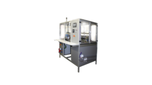
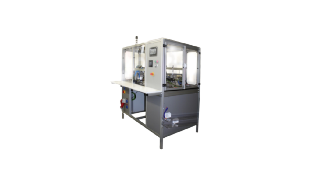
The second case is a semi-automatic machine for assembling shaver heads. The implementation tripled assembly output, although from the perspective of the operator interface a different property is more significant: settings are modified from the panel, without the involvement of a programmer. This is precisely the effect to which the recipe criterion refers – elimination of dependence on the integrator’s availability. Why the rotary table of this machine is driven by a servo drive rather than a VFD is explained in our article on servo drive sizing.
The practical side of these topics — scope of work, budget bands and lead times — is described on the HMI panels and PLC controllers service page.
Frequently asked questions
What is the difference between an HMI panel and a PLC?
The PLC performs the control logic: it reads sensor signals and controls the drives. The HMI panel functions as an interface – it presents values originating from the controller and writes operator setpoints back to it. In a typical arrangement the machine can operate without the panel, as the whole of the logic resides in the controller. This principle does not extend to panels with an integrated controller, or to those in which part of the logic has been written into panel macros.
Which HMI panel should be selected for a simple machine?
For a machine equipped with a few setpoints and a part counter, a 4.3-inch or 7-inch panel supporting the protocol of the controller in use is generally sufficient. Decisive importance attaches to matching the protocol, the touch technology and the IP rating to the conditions prevailing at the workstation; screen size remains a secondary criterion.
Can an HMI panel be replaced without replacing the PLC?
This is possible provided that the new panel supports the controller communication interface and that an address map and tag list are available. One matter is worth establishing at the outset: with older Siemens controllers (S7-300/400 over MPI or PROFIBUS) a third-party panel reads data without modification on the controller side, whereas on newer designs (S7-1200/1500) access by external devices requires enabling within the controller. This does not amount to rewriting the program, but it does require entering the controller project and must be settled before quotation. Five conditions for a panel replacement are presented in our post on machine retrofits.
Is a STOP button on the HMI panel sufficient as an emergency stop?
No. A button rendered on a touchscreen cannot serve as the emergency stop actuator – EN ISO 13850 requires a manually operated mushroom-head device with a latching function and direct opening action. The safety function itself must operate independently of the standard control system, to the Performance Level derived from the risk assessment in accordance with EN ISO 13849-1. A „STOP” element on the panel performs a process stop, not an emergency stop.
What does replacing an operator panel cost?
The panel itself generally costs a few thousand zloty excluding VAT, depending on size and specification. The second item is reconstruction of the screens together with commissioning – on a one-for-one replacement this is completed within a few working days. The whole remains a fraction of the PLN 30,000–50,000 (approx. €7,000–12,000) range applicable to a full control system retrofit, which we set out in our guide to automation costs.
Let us match a panel to your machine
Selection of a panel begins with establishing what it is to communicate with and the conditions under which it will operate. We will visit, examine the controller, the interface and the conditions at the workstation, and then propose a solution together with a screen design intelligible to the operator without additional instruction. On handover we provide the HMI project files and the access passwords, so that altering an alarm threshold in subsequent years does not require contacting us. The wider scope of work on a machine is set out in our automation and robotics services.
The visit is free of charge and without obligation, and a budget quotation is provided within 48 hours of the visit. We operate in Białystok and throughout the Podlaskie region of north-eastern Poland, and deliver larger projects elsewhere in Poland. Examples of our work are presented in completed projects.
📞 Call: +48 796 019 414
✉️ biuro@automation.net.pl
📍 Automation Dariusz Kulik, Ciesielska 2/20, 15-542 Białystok, Poland – contact details