Furniture production automation – a robotic cell for bed-box assembly
Robotic bed box assembly cell for a furniture manufacturer in Poland: +40% output, three shifts. What decided the outcome, and when a robot is the wrong answer.
Furniture production automation is usually associated with panel machining or finishing, yet the operation that most often sets the pace of a line is assembly itself. A robotic cell built for a furniture manufacturer to assemble bed boxes – the timber carcasses of storage bed bases – raised output by more than 40%, runs at a cycle of around 40–45 seconds per box and took on three-shift working without adding staff. What follows is the approach behind such a project: what determines whether it succeeds, what is invisible at the quotation stage, and when a robot is the wrong answer.
Table of contents
Furniture production automation: what makes the sector different
Furniture production automation differs from automation in the metal or food sectors in four respects, all of which have to be settled at the concept stage.
First, the material is not consistent. Timber and wood-based panels are held to dimensional tolerances far wider than anything you would accept on a turned metal part. A component may be bowed or twisted, an edge is not always straight, and a change in moisture content alters the dimensions mainly across the grain – the length of the component stays very nearly constant. Wood-based panel behaves differently from solid timber: it holds its dimensions better but swells in thickness and grips a fastener less firmly near the edge. The most common source of deviation is a change in storage conditions between delivery and assembly.
Second, variety is the rule, not the exception. A furniture manufacturer rarely produces a single size. A bed box comes in several widths, sometimes in several heights, and in versions with or without a storage compartment. A cell that handles one size has very limited use in this sector – it earns its place only on a product with high, stable volume.
Third, size and weight. Bed box components are large and awkward to grip: long, flat and prone to deflection. This has more influence on the choice of gripper and robot than the weight of the part itself. The robot class is usually decided by the permissible moment and moment of inertia at the wrist axes – calculated for the part and gripper together, the gripper often being the heavier of the two – and by the distance of the centre of gravity from the flange, rather than by nominal payload.
Fourth, the working environment. Dust and chips settle on the vision system’s optics and on sensors, and compressed air of the wrong purity class for particles, water and oil (classified under ISO 8573-1) causes more downtime in a woodworking plant than the robot ever does. Air treatment, sensor enclosures and access for cleaning are planned at the design stage, not after commissioning.
Assembling bed boxes – where the problem lies
A bed box is a structural component of an upholstered product: its geometry decides whether the slatted base seats squarely and whether the finished bed rocks. Assembly consists of bringing the components together at the corners and fastening them with staples or nails. The operation is simple, and that is precisely why it causes trouble: it is monotonous, noisy and carried out in an awkward posture, while at the same time determining the geometry of the finished product. A box assembled out of square is caught at inspection – or, in some cases, reaches the consumer.
Then come the staffing issues, rarely raised at the start of a conversation about automation. Turnover at this station is generally higher than elsewhere, training a new operator takes time, and one person’s absence halts a section of the line. Output depends not on what the machines can do, but on who has turned up for work that day.
It is also worth checking how close the components being handled come to manual handling limits. In Poland these limits are set by the regulation on occupational health and safety in manual handling operations (consolidated text, Journal of Laws of 2018, item 1139) at 30 kg for men in repetitive work and 50 kg for occasional handling, and at 12 kg and 20 kg respectively for women; where the load is carried above shoulder height the limits fall to 21 kg and 35 kg for men and 8 kg and 14 kg for women. With bed box components, however, the constraint is often not weight but size and posture, and the regulation covers those too.
How the robotic cell is built
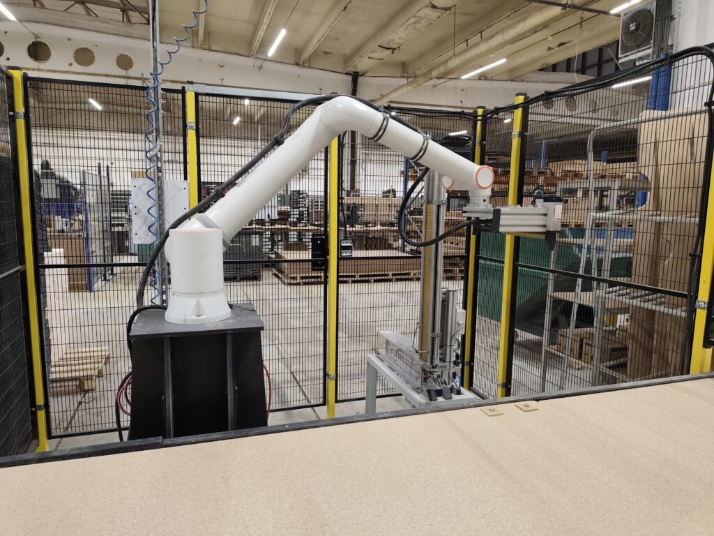
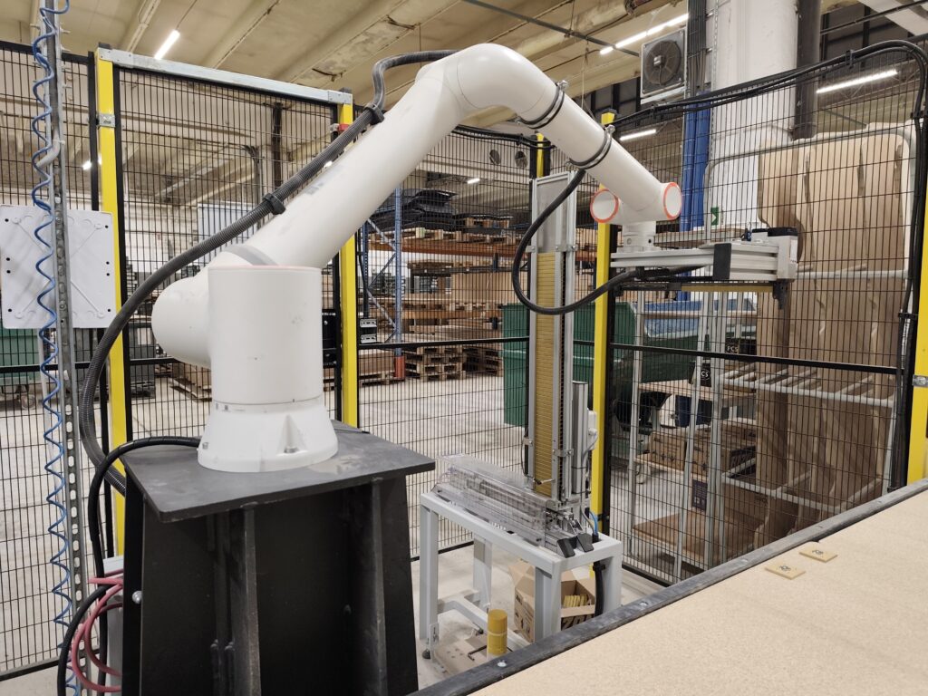
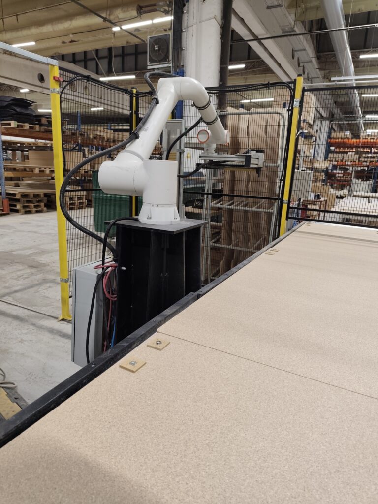
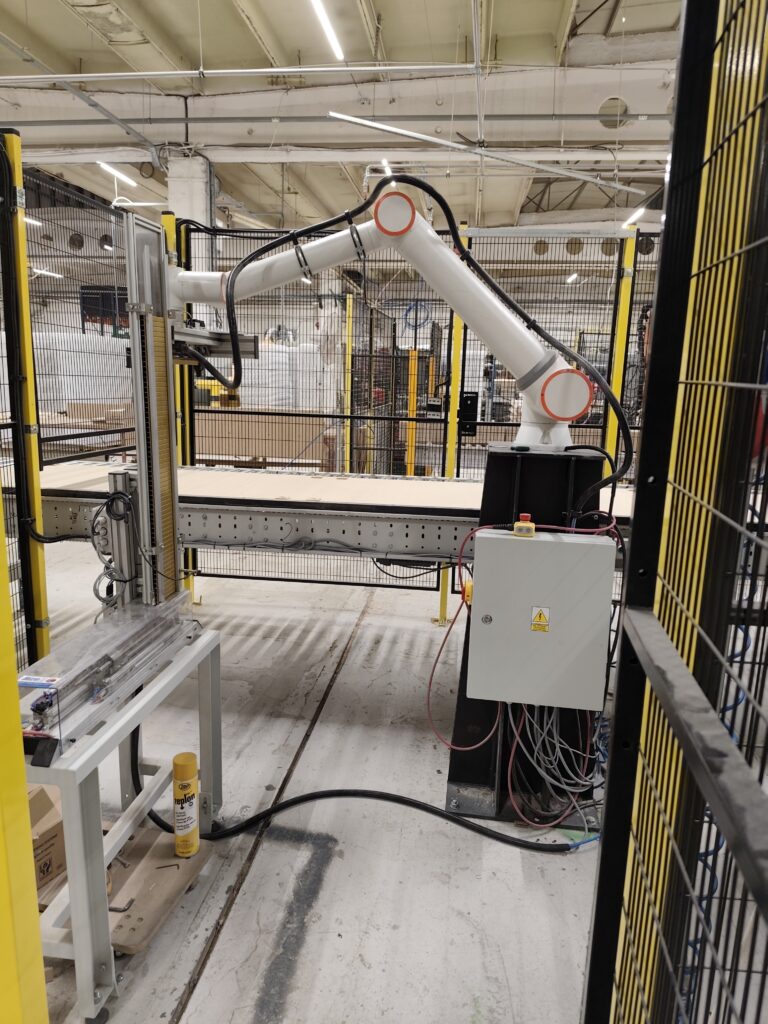
A robotic bed box assembly cell is a work cell, built around a six-axis robot, a vision system and a feeding unit, in which the robot brings bed box components together at the corners and fastens them with staples or nails, holding the box square despite variation in the material within its incoming tolerance.
The robot itself is the least troublesome part of the project – it is everything around it that decides the outcome.
- Gripper – holds a long, deflection-prone component without distorting it and without leaving a mark on a surface that is still visible in the finished product.
- Fastening unit – a stapler or nailer with its magazine (sticks of staples or a coil of nails), fastener feed and jam detection. One decision has to be taken at the concept stage: whether the tool is mounted on the robot arm or stays fixed in the jig while the robot presents the component. That choice governs cycle time and how the cell is accessed when clearing a jam. The recoil of driving a fastener acts on the component and on the gripper – and, with the tool on the arm, on the robot wrist as well – and the design has to react it, or the part shifts mid-joint.
- Vision system – establishes the actual position of the component in the feed plane rather than assuming it arrived in its nominal position. It corrects positional uncertainty only; it does not compensate for bow, twist or variation in thickness, which are taken up by mechanical location and by the compliance of the jig. Where the material can be located against hard stops, mechanical location is often cheaper and more reliable than vision.
- Locating jig and feeding – the geometry of the finished box is set by the datum faces of the jig, with the pneumatics doing no more than clamping the component against them, always to a hard stop. The clamping sequence matters: the wrong order locks an error in rather than compensating for it. The corner also has to stay square while the fastener is driven. Feeding has to deliver components in a repeatable orientation and singulated – vision corrects position, but it will not separate two boards stuck together.
- PLC control – runs the operating sequence and handles signals from the line.
- Safety-related control system – built on a safety relay or safety controller and kept separate from process control; it implements the safety functions – emergency stop, guard interlocking, safe stop – independently of the process PLC.
- In-process checking – repeatability of motion on its own confirms nothing. The cell checks that the component is present and correctly oriented before fastening, confirms that each fastener has been driven (not merely that the tool has fired), signals an empty magazine and, with knotty timber, checks that fasteners are fully seated. Without this, a missed fastener surfaces at final inspection, which is exactly where it surfaced before automation.
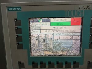
- Operator panel – gives operators the operating status and diagnostics without anyone having to fetch a service laptop. Its value lies in what the messages say: they should name the event in the language of the process – magazine empty, output buffer full, component not detected – rather than repeat controller error codes. The panel also guides the operator through the restart after a stop.
Component selection is covered in more detail on our page about robotic workstations, and the full description of this project can be found in the bed box assembly robot case study.
Safety and regulatory compliance
The starting point is a risk assessment carried out in line with EN ISO 12100: determining the limits of the cell, identifying hazards, estimating and evaluating the risk, then reducing it by the three-step method – iteratively, until an acceptable level is reached. The protective measures follow from its outcome, not the other way round.
A required performance level (PLr) is determined in accordance with EN ISO 13849-1 separately for each safety function. The category classifies the architecture of the safety-related control system and is a separate concept from PL; conflating the two is a common source of misunderstanding during acceptance testing. For the principal safety functions of such cells – the stop on opening a guard and on interrupting a light curtain – the PLr usually comes out at PL d, implemented in a Category 3 architecture, unless the risk assessment indicates otherwise.
Under EN ISO 13850, an emergency stop requires a manually actuated device with a latching action. A button on a touchscreen is not an emergency stop, no matter how it has been programmed. The emergency stop also remains a complementary protective measure – it does not replace a guard and is not credited as a risk-reduction measure in its own right.
For robotic cells the relevant standard is EN ISO 10218-1 together with EN ISO 10218-2, which covers integration. Applying a harmonised standard is voluntary: it confers a presumption of conformity with the essential requirements where that edition has been cited in the Official Journal of the European Union, while the obligation itself follows from the legal instrument, not from the standard. EN ISO 10218 is the reference both for a new installation and for a substantial modification of a cell already in service; it does not apply retrospectively to cells in service that have not been so modified.
Which legal instrument applies is decided by the date the cell is put into service: up to and including 19 January 2027 it is Directive 2006/42/EC, and from 20 January 2027 it is Regulation (EU) 2023/1230. A cell made up of a robot and the machinery working with it constitutes an assembly of machinery: before being put into service it requires its own risk assessment, technical file, instructions, declaration of conformity – an EC declaration up to 19 January 2027, an EU declaration from 20 January 2027 – and CE marking. For a cell already in service the duty rests with the end user as employer, under the minimum requirements of Directive 2009/104/EC as transposed into national law.
A separate question is the opening in the guarding through which material enters and leaves: it has to let the product through without letting a person through. This is achieved with a tunnel whose length follows from the safety distances in EN ISO 13857, or by muting a light curtain – temporarily suspending its protective function while the product passes, controlled by at least two independent sensors; muting is itself a safety function with its own PLr. Where the opening admits a whole body, it must also be impossible for a person to remain inside undetected, and the reset control must be outside the guarded space with a view of it. Equally important is planned access for clearing jams and refilling fasteners – if every such task requires a lengthy restart procedure, an incentive to defeat the interlocking device arises, and EN ISO 14119 requires that incentive to be designed out.
What this means for the end user: the risk assessment, technical file, instructions and declaration of conformity are part of the contract, not a separate line item. The declaration of conformity for the assembly of machinery is issued by the integrator as its manufacturer. The end user receives the complete documentation, and the cell carries the CE marking.
Changeover without calling the integrator
In practice, this is the point that most often decides whether a cell stays in daily use or is taken out of service. A furniture manufacturer changes size several times within a single shift, not once a quarter. If every such changeover requires the integrator, the robot stops being a tool and becomes a cost.
The answer is to give operators parameters rather than the program itself. On the operator panel, the operator selects a recipe – a stored set of settings for a given box size – and the cell reconfigures itself. A new variant is added as a further entry to the list, without touching the code.
A recipe covers only what is parametric in the software. If changing size means moving a stop, a guide rail or the spacing of suction cups, the changeover stays manual – which is why the jig is designed so that every size locates against the same datum corner and any adjustable elements are motorised. The extent to which a recipe may change positions is bounded by the space covered by the risk assessment. The recipe limit is not itself a protective measure, however – the restricted space is set by safety-rated axis and space limiting in the robot’s safety controller or by mechanical stops, and the guarding covers the whole of that space regardless of how much of it the current recipe uses.
Integrating a robot into an existing production process
A cell is rarely installed on a greenfield site. Here it was linked into a running line by conveyors and interstage buffers that decouple the robot’s cycle from that of the neighbouring stations. The buffer is part of the design, not an add-on – without it, any stoppage on one side immediately halts the other. Its capacity follows from the typical stoppage time of the neighbouring station divided by the cycle time – that is, the number of pieces the cell can produce or consume before its neighbour restarts. A buffer sized for micro-stoppages offers no protection against stoppages running to ten or fifteen minutes, so the starting point is a measurement of the actual distribution of downtime on the line, not a figure someone quotes.
Production data is exchanged with the supervisory system over Modbus TCP. The pace of work, by contrast, is set by buffer-level signals and process interlocks handled in the controller and, where they travel over a network, supervised by a watchdog at both ends. Modbus TCP is neither deterministic nor a safety protocol: it is suitable for exchanging production data, not for carrying safety-function signals. Those belong to the dedicated safety control system and, where they travel over a network, to a safety protocol such as PROFIsafe, CIP Safety or FSoE.
Installation and commissioning were planned so that production did not have to stop – at a site running three shifts that is a hard constraint, not a preference. The result at this furniture manufacturer: a cycle of around 40–45 seconds per box, output up by more than 40%, and three-shift working without adding staff. Integrating a cell with existing machinery is also discussed in our article on whether to retrofit a machine or buy a new one.
When furniture production automation pays off, and when it does not
Not every assembly station is worth automating, and we say so before quoting rather than after commissioning. The table below sets out the factors that most often settle the question in furniture production.
| Points in favour of a robot | Points against |
|---|---|
| A finite, known list of product sizes (a dozen or several dozen – it does not matter, as long as they are written down) | One-off production, every item different |
| Two or three shifts | A single shift, seasonal production |
| The operation is the bottleneck in the line | The bottleneck lies elsewhere |
| High turnover and absenteeism at the station | A stable, experienced team |
| Incoming material cut to tolerance and sorted | Cutting tolerances out of control, material unsorted |
| Maintenance cover available on every shift | No maintenance cover beyond the first shift |
| Room for a guarded area, and spare compressed-air and electrical capacity | No room, or no headroom in the utilities |
A practical rule: where at least three of the seven conditions in the left-hand column are met, the cell is worth quoting for. Two conditions settle the matter on their own – if the bottleneck lies elsewhere, or production is one-off, the remaining entries do not matter.
Where the right-hand column prevails, an intermediate solution is usually the sounder choice: a semi-automatic station supporting the operator, better material feeding, or retrofitting the control system of the machine that actually limits throughput. It is also worth comparing a robot with dedicated equipment: for a single, unchanging size, a nailing machine or a case clamp is often faster and cheaper than a robotic cell. The robot has the advantage where variants differ not merely in size but in construction – the number of components or the placement of fasteners – and where the same arm is expected to take on a further operation in time. For a change of size alone, a nailing machine with motorised stops does the job just as well. We apply the same logic when assessing when robotic palletising pays off.
What decides whether a cell is used every day is the amount of changeover handed to the operators. What decides whether it is accepted at all is something quite different: most of the time goes not into programming the robot, but into agreeing exactly what the cell should do when things go wrong – a defective component, a full buffer, a cycle interrupted by the operator, an empty fastener magazine. Each case needs a decision on who decides and what happens to the part. An end user arriving at the meeting with answers to those questions shortens the project more than any choice of hardware.
Frequently asked questions
How much does a robotic bed box assembly cell cost?
A robotic cell typically means an outlay in the region of PLN 150,000–500,000 (roughly €35,000–€115,000 at current rates) and three to six months of work. Where a project falls within that range depends on the number of sizes handled, the extent of the protective measures the risk assessment calls for, and how the cell is linked into the existing line. The site visit is free of charge, and a quotation with cost ranges and an estimated payback period follows within 48 hours of the visit.
Can a robot cope with timber of varying dimensions?
Yes, provided the locating jig is properly designed and the positional uncertainty of the incoming component is taken out either by a vision system or by locating against hard stops. Bow, twist and variation in thickness are taken up by mechanical location and the compliance of the jig. Without both of these, the cell will only work on material of consistent geometry, which furniture production does not offer.
Can the robot handle several box sizes?
Yes, provided the list of sizes is known at the design stage. Each variant is stored as a recipe on the operator panel, and changeover comes down to picking an entry from a list – provided the adjustable elements of the jig are motorised and every size locates against the same datum corner. What matters is establishing at the outset which parameters are to be editable without involving the integrator, and within what limits – the boundary is the space covered by the risk assessment.
Do we need a robot programmer to run the cell?
No. The cell is operated, after training, by the person who previously did the job by hand. The panel shows the operating status and diagnostic messages, so the team can deal with routine situations unaided. The cell is also set up for remote diagnostics over an internet connection – the integrator can check the state of the controller and the robot without visiting the site. The end user receives the complete documentation of the cell: the risk assessment, as-built drawings and schematics, the instructions and the declaration of conformity; the cell carries the CE marking.
Does production have to stop during installation?
Not necessarily. The work is planned in stages and the cell is linked into the line during production windows agreed with the end user. In the project described here, integration took place without interrupting production.
Does modifying an existing cell require new CE marking?
Not always. It depends on whether the change amounts to a substantial modification. The test has two limbs: a new hazard must arise or the existing risk must increase, and the protective measures in place must be insufficient, so that new ones have to be added or rebuilt. Adding a simple guard without interfering with the safety-related control system is not a substantial modification. We assess each case before work begins.
Can the cell be extended later?
Yes, if this was provided for in the design. Spare capacity in the control system, spare inputs and outputs, room in the cabinet and headroom in the compressed-air supply cost little at the build stage and make it easy to add another operation later. Spare reach on the robot costs more than it appears: moving up a robot size also enlarges the guarded area and the floor space occupied. An extension always requires the risk assessment to be updated; only its outcome decides whether the change is a substantial modification entailing a fresh conformity assessment.
What a bed box assembly cell costs and how to get a quotation
Where a project falls within the PLN 150,000–500,000 range (roughly €35,000–€115,000 at current rates) depends above all on the number of sizes, the extent of the protective measures and how the cell is linked into the line; delivery takes three to six months. What goes into that figure is broken down in our article on how much production line automation costs.
If assembly, fastening or packing sets the pace of your line, start by showing us the process. We come to you, measure cycle times and say plainly whether automating that particular operation makes sense – including when the answer is no. The visit and the initial assessment are free of charge and commit you to nothing; a quotation with cost ranges and an estimated payback period follows within 48 hours of the visit.
Call +48 796 019 414, write to biuro@automation.net.pl or use the contact form. We are an industrial automation integrator based in Poland, delivering projects throughout the country.