Servo or VFD? Drive Selection for a Production Machine
A VFD regulates speed; a servo drive controls position, speed and torque. When a VFD is enough, when a servo is needed and how to size a servo drive.
Servo or VFD? A variable-frequency drive (VFD, also called an inverter) is enough when the drive only has to regulate speed; a servo drive is needed when an axis has to stop quickly and accurately at a set point, run in synchronism with another axis or control torque. A VFD with an induction motor usually regulates speed in an open loop; a servo drive controls position, speed and torque in a closed feedback loop. This article covers the differences, the range of applications of both solutions, the intermediate options – including a machine on stepper motors that lose position – and servo drive sizing step by step; two completed machines – a semi-automatic assembly machine with a rotary table and a three-axis CNC milling machine – illustrate the division of roles between the two kinds of drive.
Table of contents
Servo or VFD – how they work and how they differ
A VFD supplies an induction motor with voltage of adjustable frequency and amplitude, and so varies its speed smoothly. A plain VFD has no measurement of shaft position: in V/f control the motor runs with a slip that depends on the load, sensorless vector control estimates speed and rotor flux from the measured currents and voltages and gives full torque from about 0.5 Hz, and only vector control with an encoder closes the speed loop and holds full torque at standstill. In continuous operation at low speeds both forms of vector control require a separately driven motor fan.
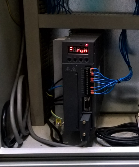
A servo drive is a set consisting of a servo motor (usually a permanent-magnet synchronous motor), a built-in encoder and a servo amplifier that regulates current, speed and shaft position in a closed loop. Colloquially, ‘servo’ means the whole set. The controller commands a position, and the servo amplifier compares it with the encoder reading and corrects the error in cycles of microseconds for the current loop and milliseconds for the position loop. A low-inertia rotor and a short-term overload capacity of 2–3.5 times rated torque (for seconds, up to a defined speed) give dynamics that an induction motor of comparable torque cannot match. Series with an incremental encoder, such as the Xinje DS2, require homing after power-on; a multi-turn absolute encoder (an option in newer series, e.g. DS5, with the revolution count kept by a battery in the encoder cable) retains the position information after power-off.
The main differences between a VFD and a servo drive:
| Criterion | VFD + induction motor | Servo drive |
|---|---|---|
| Controlled variable | speed; torque only in vector mode | position, speed and torque |
| Feedback | none, or optional encoder | always – encoder built into the motor |
| Positioning repeatability | coarse, on sensors; a brake where a force acts at standstill (±1–2 mm) | tenths to hundredths of a millimetre, depending on the mechanics |
| Torque at zero speed | full only with an encoder; sensorless from about 0.5 Hz; in continuous operation at low speeds – with a separately driven fan | full, including at standstill |
| Dynamics, start–stop cycles | limited by rotor inertia | very high, short-term overload 2–3.5× |
| Axis synchronisation | approximate | electronic gearing and camming |
| Cost of a set of comparable torque | lowest, standard motor | several times higher |
| Typical use | conveyors, pumps, fans, spindles, agitators | positioning axes, rotary tables, feeders, CNC, robots |
The range of VFD applications
A VFD is the right choice wherever the drive’s task is to hold a set speed or change it smoothly and the shaft position does not matter: belt conveyors and feeders, pumps, fans, agitators, machine-tool spindles, pull rolls, the main drives of continuously running packaging machines. The advantage lies not only in price but in the motor – a standard induction motor is held in stock by most suppliers, is simple in construction and needs no encoder cable. The limitation is cooling: a motor with its own shaft-mounted fan overheats in prolonged operation below about 20–30 Hz and needs a separately driven fan or torque derating.
A VFD is also enough for coarse positioning if the machine tolerates an uncertainty of the order of millimetres: a conveyor approaching a sensor at creep speed (a slow-down sensor and a stop sensor give a repeatability of ±1–2 mm, dependent on load), a lift delivering parts to a level confirmed by a sensor, an adjustment axis repositioned once per shift. Where a force acts on the axis at standstill (a lift, a clamp), a mechanical brake that holds the position after stopping is required, because an induction motor without an encoder will not hold a load at standstill. A VFD is no longer sufficient when the cycle requires frequent starts and stops with high dynamics, when torque has to be controlled at very low speed, or when two axes have to move in a defined relationship to each other.
Servo drive applications
A servo drive is essential wherever the drive has to stop at a set point with a repeatability of tenths or hundredths of a millimetre, execute a move in a precisely defined time, or work in relation to another axis. Typical servo drive applications in production machines are:
- rotary and indexing tables – rotation by a set angle to the next station, with the position held during the operation;
- linear feed and positioning axes – intermittent (index) feeders, pick-and-place manipulators, X/Y/Z gantry axes;
- cutting and marking on the fly – a tool axis synchronised with the movement of the material (electronic gearing or camming, flying shear);
- operations with torque control – press-fitting, clamping, tightening to a torque limit;
- interpolated axes – CNC machine tools, contour dispensing equipment, plotters.
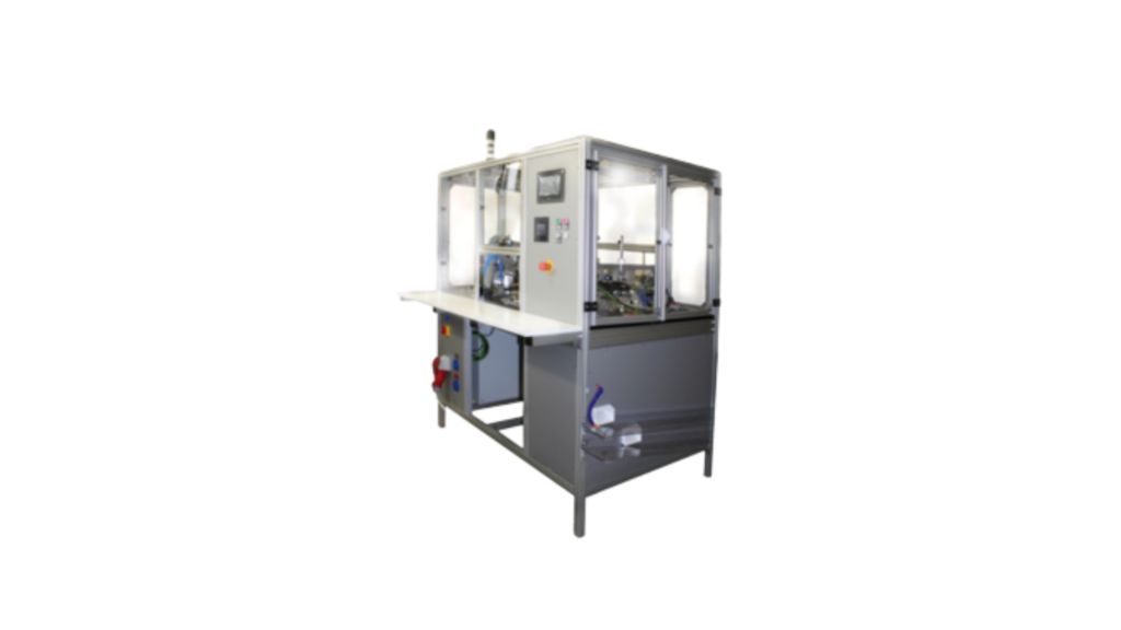
Two completed machines mark the boundary between the two solutions. In the semi-automatic machine for assembling shaver heads the table carrying the parts is turned by a Xinje DS2 series servo drive: each station – driving in the metal plate, pressing in the button with its spring, vision inspection – requires the part to be positioned to tenths of a millimetre, and the position has to be held during the operation. A VFD-driven table stopping on sensors does not provide that repeatability. Taken as a whole, the semi-automatic machine delivered a threefold increase in output compared with manual assembly and reduced production rejects to zero thanks to component presence checking.
The three-axis CNC milling machine for aluminium muntins (glazing bars) combines both kinds of drive in one machine: the three interpolated axes are driven by Xinje DS5 series servo drives under our in-house CNC control system, while the 2 kW spindle is driven by a VFD – all that is required of the spindle is a constant rotational speed, not a position. The machine processes profiles 25–60 mm wide and up to 2,500 mm long at feed rates of up to 500 mm/s with a positioning accuracy of ±0.05 mm. Servo where position matters, VFD where speed matters – that is a design rule, not a compromise.

Intermediate options and a machine on stepper motors
A vector VFD with an encoder card closes the speed loop on an induction motor fitted with an encoder: it gives full torque at zero speed and positioning of slow axes to tenths of a millimetre without a servo motor. It works well in lifts, adjustment axes and positioning conveyors, but not in dynamic cycles – the inertia of the induction rotor remains unchanged. A servo drive with an induction motor (a heavy-duty induction motor fitted with an encoder, plus a servo amplifier) is used at high power ratings, where a permanent-magnet motor would be uneconomical.
A closed-loop stepper motor is an economical alternative to a servo drive on axes with low torque and moderate speed: an encoder detects lost steps and the stepper driver works like a simple servo amplifier. A stepper motor, however, has no short-term overload capacity and its torque falls with speed – above a few hundred revolutions per minute or a dozen or so newton-metres the servo drive’s advantage becomes clear. Hence the rule for a machine that loses position: if the torque required at working speed lies within the stepper motor’s characteristic and the motor loses steps only occasionally (resonance, no torque margin in open loop), a closed-loop stepper motor is usually enough. If the required torque exceeds that characteristic or the cycle needs a short-term overload, a servo drive is needed.
Replacing a stepper motor with a servo drive is a common modernisation, but it does not come down to swapping the motor. The servo motor is selected by torque, not by flange size – a stepper motor has a high holding torque at standstill, and a servo motor of the same flange size may be weaker. The servo amplifier accepts a pulse signal of the same type, but the signal level (5 V line driver or 24 V) and the pulse frequency must be matched, an electronic gear ratio set, the enable, alarm and in-position signals handled in the program, and the servo loops tuned. The PLC with pulse outputs usually stays, and the scope of work on each axis is set after an inspection. The machine needs a new conformity assessment when the change creates a new hazard or increases the risk and reducing it requires protective measures to be added or rebuilt with changes to the safety-related control system. The higher dynamics of a servo-driven axis can be such an increase; this is decided by a risk assessment of the change, which is carried out in every case.
Servo drive sizing step by step
Servo drive sizing starts from the motion profile, not from the catalogue, and is iterative – the gear ratio changes torque, speed and inertia at the same time:
- Motion profile – travel, cycle time, dwell time, profile shape (trapezoidal or S-curve); these determine the maximum speed and the acceleration.
- Transmission and gear ratio – a ball screw on short axes with high force, a toothed belt on long and fast axes, a rack and pinion above a few metres; a planetary gearbox reduces the inertia referred to the motor shaft by the square of the ratio, but adds its own inertia and backlash, and in a precision version often costs more than the motor.
- Torques – the load torque (friction, process force, gravitational component) and the dynamic torque from the inertia of the whole system (rotor, gearbox, load referred to the motor shaft) and the acceleration; the inertia ratio of load to rotor – as a guide up to 5–10:1 for dynamic axes, more for slow and stiff axes.
- Motor check – the RMS torque of the cycle, including the torque held at standstill, must be below the rated torque with a 20–30% margin (catalogue values apply to continuous duty S1 at 40 °C), and the peak torque and speed must lie within the intermittent zone of the torque–speed characteristic.
- Brake and mechanics – a vertical axis requires a holding brake in the motor (not a working brake) or a self-locking transmission; absolute accuracy is determined by gearbox and screw backlash, belt compliance and mounting stiffness, not by encoder resolution.
- Interface and supply – pulse-and-direction for a few axes (note the maximum output frequency of the controller), a motion bus such as EtherCAT for many interpolated and synchronised axes, a position table over Modbus for simple axes; the voltage class of the servo amplifier (220 or 400 V) must match the supply and the motor. The braking resistor is sized from the braking energy and the frequency of stops, and inadequate cable screening – without 360° gland earthing – is a common cause of encoder faults after commissioning.
A common sizing error is choosing the motor by power: a high-speed motor of high power but low rated torque, selected without a gearbox, will not hold the pressing load at standstill, while a motor oversized ‘to be on the safe side’ has a rotor inertia greater than the load and does not use its dynamics. Selecting the controller for the number and type of axes is discussed in our article PLC controllers – types, programming and selection, and selecting the operator panel in HMI Panels in Practice – How to Choose an Operator Panel.
Cost, energy and drive safety
Cost. A servo drive set is several times more expensive than a VFD with a motor of comparable torque, and the encoder cable, often a planetary gearbox and a controller with axis support have to be added; an induction motor is usually available off the shelf, while a servo drive and a precision gearbox have longer delivery times that depend on the supplier. The balance shifts when a servo replaces mechanical components: a servo-driven rotary table needs no Geneva mechanism (a mechanical indexer) and allows a variable index, but the drive then has to hold the position under load; a servo axis needs no adjustable stops for every format (limit switches and fixed end stops remain), and changing the axis positions for another format comes down to selecting a recipe on the panel. In a machine with several formats this effect can offset the difference in drive price.
Energy. Induction motors and VFDs are subject to Commission Regulation (EU) 2019/1781, as amended, on ecodesign. From 1 July 2021 three-phase induction motors of 0.75–1,000 kW must meet at least efficiency class IE3 (motors from 0.12 to below 0.75 kW, class IE2), and variable-speed drives (the regulation’s term for VFDs) with a three-phase input for motors of 0.12–1,000 kW must meet class IE2; from 1 July 2023 motors of 75–200 kW with 2, 4 or 6 poles, except brake motors and explosion-protected motors, must meet IE4. Permanent-magnet synchronous servo motors are outside the scope of the regulation, which covers induction motors. An induction brake motor is usually subject to IE3, and a servo amplifier with a three-phase supply is subject to IE2 only if it meets the definition of a VFD, i.e. it can also supply an induction motor; regenerative drives are excluded. In start–stop cycles energy is saved above all by regeneration during braking on a DC bus shared by several axes.
Safety. Some VFDs and servo amplifiers offer the safety sub-functions described in EN 61800-5-2:2017, and their scope depends on the model and version of the drive: STO (safe torque off – the drive does not supply the motor with energy that can generate torque; a stop category 0 under EN 60204-1:2018), SS1 (safe stop 1 – deceleration on a ramp followed by STO; stop category 1, in the SS1-t variant without monitoring of the deceleration, in SS1-r with monitoring of the deceleration and in SS1-d with the deceleration controlled by the safety function) and SLS (safely limited speed – monitoring that speed does not exceed a limit, e.g. in setting mode with a guard open). These are sub-functions of the drive – the required performance level (PLr) is determined from the risk assessment under EN ISO 13849-1:2023 separately for each function, and the whole function, from the push-button or guard through the safety relay to the drive, must achieve it. Where that level is achieved, the STO input can replace a contactor in the motor circuit, but it does not remove the voltage from the motor terminals and does not replace the isolator for work on the motor; after STO the motor coasts freely. On a vertical axis the brake in the motor is a holding brake – if holding the axis is a safety function, its control is implemented with the SBC (safe brake control) sub-function and the stop as the sequence: SS1, brake closure, STO.
Electromagnetic compatibility. The requirements are defined by EN IEC 61800-3:2023: a site supplied from its own transformer substation is the second environment and a category C3 drive suffices there, while a workshop supplied directly from the public low-voltage network that also supplies residential buildings is the first environment and requires category C1 or C2; the category applies to the whole system – drive, filter and screened motor cable up to the length permitted by the manufacturer.

Frequently asked questions
What is the difference between a servo drive and a VFD?
A VFD regulates the speed of an induction motor by changing the supply frequency and usually does not measure the shaft position. A servo drive controls the position, speed and torque of a servo motor in a closed loop with an encoder built into the motor, so it stops at a set point with a repeatability of tenths or hundredths of a millimetre (depending on the mechanics) and holds full torque at standstill. A VFD is cheaper and sufficient for speed control and coarse positioning; a servo drive is essential for accurate positioning of dynamic axes and for axis synchronisation.
VFD or servo for a conveyor, a rotary table and a feed axis?
A conveyor, pump, fan or spindle – a VFD, because speed is what matters. An indexing table, a feed axis stopping at a set point and synchronised axes – a servo drive, because position is what matters. A slow axis with coarse positioning, for example a lift or an adjustment axis – a vector VFD with an encoder (and a brake if the axis is loaded at standstill), as an intermediate option.
Can a VFD position an axis?
Yes, to a limited extent: a vector VFD with an encoder card and an induction motor fitted with an encoder positions slow axes to tenths of a millimetre and holds torque at standstill. Without an encoder, positioning relies on sensors and creep speed – with a mechanical brake as well where a force acts on the axis at standstill – and has a repeatability of ±1–2 mm, depending on load. Dynamic, interpolated or synchronised axes need a servo drive.
Can a servo motor be run from a VFD?
Technically yes, but the result is not a servo drive: some VFDs can run a permanent-magnet motor without an encoder in speed control, but a VFD without a motor encoder will not close the position loop or hold torque at standstill; accurate positioning of dynamic axes requires a servo amplifier with the motor’s encoder. Conversely, using a servo drive where a constant speed without dynamic requirements is all that is needed is possible but usually uneconomical.
Where does servo drive sizing start?
Servo drive sizing starts from the motion profile – travel, cycle time, dwell time and acceleration – and from the load torque, not from the power in the catalogue. Next come the transmission and gear ratio, the RMS torque of the cycle with a margin and a check of the inertia ratio; only then are the motor and servo amplifier chosen, and finally the control interface and the supply.
What is STO in a VFD or servo drive?
STO (safe torque off) is a safety sub-function under EN 61800-5-2 which, when the enable signal is removed, cuts off the drive signals to the power stage so that the motor cannot produce torque – a stop category 0. Where the whole safety function achieves the required PLr, STO can replace the contactor in the motor circuit and shorten the restart time, but it does not brake actively and does not remove the voltage from the motor terminals; a vertical axis needs a brake, and a controlled stop is provided by the SS1 sub-function. The required performance level PLr follows from the risk assessment under EN ISO 13849-1.
Drive selection for your machine – a quotation
As a rough guide, a semi-automatic machine with servo-driven axes costs PLN 50,000–150,000 (roughly €12,000–35,000; 2–4 months from signing the contract to acceptance), and replacing the drives and controls in an existing machine PLN 30,000–50,000 (roughly €7,000–12,000; 1–3 months), depending on the number of axes; a special-purpose machine with interpolated axes is quoted according to scope. Our article Machine Retrofit or a New Machine? discusses when replacing drives pays off better than buying a new machine; the scope of services is described on the offer pages machine retrofit and modernisation, HMI panels and PLC controllers and CNC milling.
If your machine loses position, a changeover to another format takes hours, or you are planning a new cell and do not know whether a VFD will be enough – show us the process. We visit, inspect the machine, establish the cycle and the loads, and within 48 hours of the visit send a preliminary quotation with the scope of work and an indicative lead time, showing on which axes a servo is essential and on which a VFD is enough. The visit and the preliminary assessment are free of charge and without obligation.
Call +48 796 019 414, write to biuro@automation.net.pl or fill in the contact form. We have been in business for 15 years and carry out projects throughout Poland.